draw in 3d autocad 2013
Affiliate 1. Introduction to 3D Pattern
Welcome to the fantastic earth of 3D! AutoCAD is an excellent software for creating second projects in all technical areas, merely instead of 2d representation, isn't it much better if nosotros could create accurate 3D models, view them from all perspectives (fifty-fifty from inside), and go 2D drawings easily? With AutoCAD we can!
The topics covered in this chapter are every bit follows:
-
The importance of the third coordinate
-
How to choose and manage 3D workspaces
-
Why object properties are central in 3D
-
How auxiliary tools (osnap, ortho, and others) can ease the piece of work in 3D
-
second commands in a 3D world
-
How to apply linear 3D commands
-
How to create great 3D models
The Z coordinate
3D is all about the third Z coordinate. In 2D, we only intendance for the X and Y axes, but never used the Z axis. And nearly of the time, we don't even use coordinates, just the top-twenty AutoCAD commands, the Ortho tool, and then on. But in 3D, the correct use of coordinates can substantially accelerate our work. We will beginning briefly encompass how to introduce points by coordinates and how to extrapolate to the tertiary dimension.
Accented coordinates
The location of all entities in AutoCAD is related to a coordinate organisation. Whatever coordinate system is characterized past an origin and positive directions for the X and Y axes. The Z axis is obtained directly from the Ten and Y axes by the right-hand rule: if we rotate the right hand from the X axis to the Y axis, the pollex indicates the positive Z direction.
Motion picture that when prompting for a point; too specifying it in the drawing area with a pointing device such as a mouse, we can enter coordinates using the keyboard.
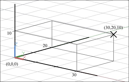
The format for the absolute Cartesian coordinates related to the origin is defined past the values of the three orthogonal coordinates, namely, X, Y, and Z, separated past commas:
X coordinate, Y coordinate, Z coordinate
The Z coordinate can be omitted.
For instance, if nosotros define a point with the absolute coordinates 30, 20, and 10, this means 30 absolute is in the Ten direction, 20 is in the Y direction, and 10 is in the Z management.
Relative coordinates
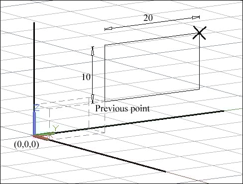
Frequently, nosotros desire to specify a betoken in the coordinates, just ane that is related to the previous point. The format for the relative Cartesian coordinates is defined by the symbol AT ( @ ), followed past increase values in the three directions, separated by commas:
@Ten increment, Y increment, Z increment
Of course, one or more than increments tin be 0. The Z increment tin be omitted.
For example, if we define a signal with relative coordinates, @0,20,ten, this means in relation to the previous indicate, 0 is in 10, xx is in Y, and ten is in Z directions.
Signal filters
When nosotros want to specify a point but decompose it step-past-stride, that is, separate its coordinates based on different locations, we may apply filters. When prompting for a point, we admission filters by digitizing the X, Y, or Z axes for individual coordinates, or XY, YZ, or ZX for pairs of coordinates. Another way is from the osnap menu, CTRL + mouse right-click, and and so Bespeak Filters . AutoCAD requests for the remaining coordinates until the completion of betoken definition.
Imagine that we desire to specify a point, for case, the center of a circle, where its Ten coordinate is given by the midpoint of an border, its y coordinate is the midpoint of another edge, and finally its Z coordinate is any bespeak on a tiptop face up. Assuming that Midpoint osnap is predefined, the dialog should be:
Command: CIRCLE Specify center signal for circle or [3P/2P/Ttr (tan tan radius)]: .X of midpoint of edge (need YZ): .Y of midpoint of edge (need Z): any bespeak on elevation face Specify radius of circle or [Bore]: value
Workspaces
AutoCAD comes with several workspaces. Information technology'southward up to each of u.s.a. to choose a workspace based on a classic environment or the ribbon. To alter workspaces, we tin can pick the workspace switching button on the status bar:
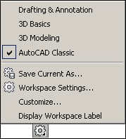
There are other processes for acceding this command such as the workspaces list on the Quick Admission Toolbar (title bar), the Workspaces toolbar, or past digitizing WSCURRENT, just the access shown is consistent among all versions and ever available.
Classic surround
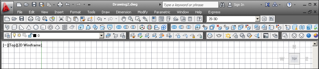
The classic environs is based on the toolbars and the menu bar and doesn't use the ribbon. AutoCAD comes with AutoCAD Classic workspace, but information technology's very simple to adapt and view the suitable toolbars for 3D.
The advantages of using this environment are speed and consistency. To show another toolbar, nosotros right-click over whatsoever toolbar and choose it. Typically, we desire to accept the post-obit toolbars visible besides Standard and Layers: Layers II, Modeling, Solid Editing, and Render:
Ribbon surroundings
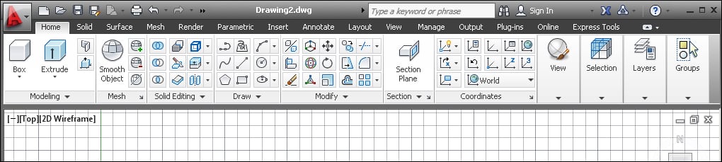
Since the 2009 version, AutoCAD also allows for a ribbon-based environment. Normally, this environs uses neither toolbars nor the menu bar. AutoCAD comes with two ribbon workspaces, namely, 3D Basics and 3D Modeling; the first existence less useful than the second.
The advantages are that we have consistency with other software, commands are divided into panels and tabs, the ribbon can be collapsed to a unmarried line, and it includes some commands not available on the toolbars. The disadvantage is that equally it's a dynamic environment, nosotros often have to activate other panels to access commands and some important commands and functions are not always visible:
Note
When modeling in 3D, the layers list visibility is almost mandatory. We may add this list to the Quick Admission Toolbar by applying the CUI command or by right-clicking above the command icon nosotros want to add. Another way is to pull the Layers panel to the drawing surface area, thus making it permanently visible.
Layers, transparency, and other properties
When we are modeling in AutoCAD, the ability to command object properties is essential. Later some hours spent on a new 3D model, nosotros can have hundreds of objects that overlap and obscure the model's visibility. Here are the nigh of import properties.
Layers
If a correct layers application is fundamental in 2D, in 3D it assumes extreme importance. Each type of 3D object should be in a proper layer, thus allowing us to control its properties:
-
Proper name : A good piece of advice is to not mix 2D with 3D objects in the same layers. So, layers for 3D objects must exist easily identified, for instance, past adding a 3D prefix.
-
Freeze/Thaw : In 3D, the density of screen information can exist huge. So freezing and unfreezing layers is a permanent procedure. It'south ameliorate to freeze the layers than to turn off because objects on frozen layers are non processed (for instance, regenerating or counting for
ZOOMExtents ), thus accelerating the 3D process. -
Lock/Unlock : It'south quite abrasive to notice that at an advanced phase of our project, our walls moved and caused several errors. If nosotros need that information visible, the best mode to avoid these errors is to lock layers.
-
Color : A adept and logical color palette assigned to our layers tin improve our understanding while modeling.
-
Transparency : If nosotros want to see through walls or other objects at the creation procedure, we may give a value between 0 and 90 pct to the layers transparency.
Last but non least, the best and the easiest process to assign rendering materials to objects is by layer, so another skillful point is to apply a correct and detailed layer scheme.
Transparency
Transparency, as a belongings for layers or for objects, has been bachelor since Version 2011. Too its utility for layers, it can also be practical directly to objects. For instance, nosotros may accept a layer chosen 3D-SLAB and only want to meet through the upper slab. We can change the objects' transparency with Properties ( Ctrl + ane ).
To run into transparencies in the drawing area, the TPY button (on the status bar) must be on.
Visibility
Another recent improvement in AutoCAD is the ability to hide or to isolate objects without changing layer properties.
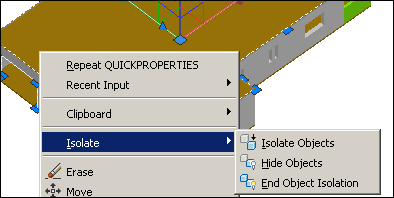
We select the objects to hide or to isolate (all objects not selected are hidden) and correct-click on them. On the cursor menu, we cull Isolate and so:
-
Isolate Objects : All objects not selected are invisible, using the
ISOLATEOBJECTScommand -
Hide Objects : The selected objects are invisible, using the
HIDEOBJECTScommand -
Terminate Object Isolation : All objects are turned on, using the
UNISOLATEOBJECTScommand.
There is a small lamp icon on the status bar, the second icon from the right. If the lamp is crimson, it ways that there are subconscious objects; if it is yellow, all objects are visible:
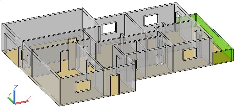
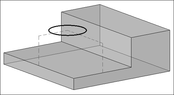
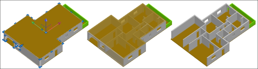
Shown on the following image is the application of transparency and hide objects to the left wall and the upper slab:
Auxiliary tools
AutoCAD software is very precise and the right application of these auxiliary tools is a key gene for good projects. All users should be familiar with at least Ortho and Osnap tools. Following is the application of auxiliary tools in 3D projects complemented with the first exercise.
OSNAP, ORTHO, POLAR, and OTRACK auxiliary tools
Let's start with object snapping, probably the most frequently used tool for precision. Every time AutoCAD prompts for a betoken, we tin admission predefined object snaps (also known every bit osnaps) if the OSNAP button on the status bar is on. To modify it, we only have to click on the OSNAP button or printing F3 . If we desire an individual osnap, we tin can, among other ways, digitize the first three letters (for instance, MID for midpoint) or apply the osnap menu ( CTRL + right-click). Osnaps work everywhere in 3D (which is great) and is especially useful is the Extension osnap manner, which allows you to specify a point with a altitude in the direction of any edge.
Just what if nosotros desire to specify the projection of 3D points onto the working XY airplane? Easy! If the OSNAPZ variable is gear up to 1, all specified points are projected onto the plane. This variable is non saved and 0 is assigned as the initial value.
More than swell news is that ORTHO ( F8 ) and POLAR ( F10 ) work in 3D. That is, we can specify points past directing the cursor forth the Z axis and assign distances. Lots of @ spared, no?
OTRACK ( F11 ), used to derive points from predefined osnaps, also works along the Z-axis management. We suspension over an osnap and can assign a distance along a specific direction or merely obtain a crossing:
3DOsnap tool
Starting with Version 2011, AutoCAD allows you to specify 3D object snaps. Too, here nosotros can admission predefined 3D osnaps keeping 3DOSNAP ( F4 ) on, or nosotros can access them individually. In that location are osnaps for vertices, midpoints on edges, centers of faces, knots (spline points), points perpendicular to faces, and points nearest to faces.
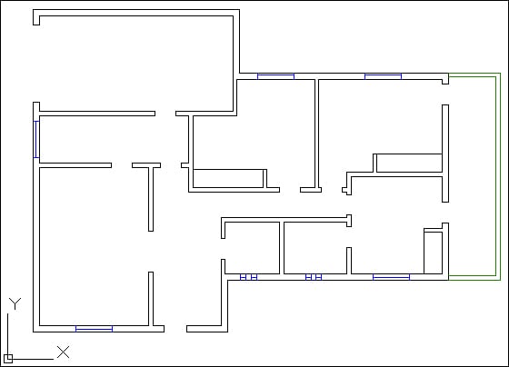
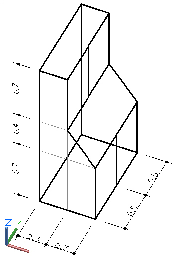
Exercise 1.1
Using the LINE command, coordinates, and auxiliary tools, let'south create a cabinet skeleton. All dimensions are in meters and nosotros starting time from the lower-left corner. The ORTHO or POLAR button must exist on and the OTRACK and OSNAP buttons with Endpoint and Midpoint predefined.
Note
As in 2d, rotating the bicycle mouse forward, nosotros zoom in; rotating the wheel backward, nosotros zoom out; all related to cursor position. To automatically orbit effectually the model, nosotros hold downwards SHIFT and the wheel simultaneously. The cursor changes to two pocket-size ellipses and and so nosotros drag the mouse to orbit around the model. Visualization is the discipline of the next chapter.
-
We run the
LINEcommand at any point, block management 10 ( POLAR or ORTHO ) and assign the distance:Control: LINE Specify first betoken: any betoken Specify next bespeak or [Undo]: 0.6
-
We block the Z direction and assign the distance:
Specify next point or [Disengage]: 0.7 -
The all-time style to specify this point is with relative coordinates:
Specify next point or [Close/Undo]: @-0.3,0,0.iv -
Nosotros block the Z management and assign the distance:
Specify adjacent point or [Shut/Undo]: 0.vii -
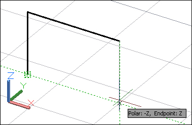
The best way to close the left polygon is to break over the kickoff indicate, move the cursor upwards to find the crossing, with Polar or Ortho coming from the last betoken, and apply Close choice to shut the polygon:
Specify next point or [Close/Undo]: indicate with OTRACK Specify next signal or [Close/Undo]: C
-
We copy all lines one meter in the Y direction:
Control: Re-create Select objects: Specify contrary corner: half dozen constitute Select objects: Enter Electric current settings: Copy mode = Multiple Specify base point or [Displacement/fashion] <Displacement>: bespeak Specify second point or [Array] <use first signal as displacement>: ane Specify 2nd point or [Assortment/Exit/Undo] <Exit>: Enter
-
Nosotros complete the cabinet skeleton past cartoon lines between endpoints and midpoints:
Application of 2D commands
Tin those everyday commands exist used in 3D? Of form they can! We have already seen the LINE control, layers, and other properties. Let's see some particularities and 3D applications and learn that a whole bunch of known commands can also exist applied.
Drawing commands
Basically, all drawing commands tin exist used in 3D, provided that we accept the correct working plane, LINE being the exception.
The LINE control tin can have its endpoints anywhere, so it's a real 3D command. But circles, arcs, and polylines (including polygons and rectangles) are fatigued on the working plane (called active coordinate system) or a plane parallel to the working plane.
Editing commands
Here is the list of the most important editing commands that work the same way in 2D or 3D: ERASE, MOVE, COPY, SCALE, Join, EXPLODE, and BREAK.
Some commands work only on the objects plane, not necessary the active working plane. Examples are FILLET, CHAMFER, and OFFSET.
In that location are as well some that work but in relation to the active working plane such every bit MIRROR, ARRAYCLASSIC (Array before version 2012), and ROTATE.
Next are editing commands that have special 3D features:
-
TRIMandEXTEND: Both commands have an choice, Project , which specifies if linear objects are cut or extended to the boundaries related to the current coordinate organization or the current view. This allows for cutting or extending objects that, in the electric current view, seems to be on the same aeroplane, just are really on different planes. -
ARRAY: This command changed a lot in version 2012. At present, we have 3 different commands for rectangular, polar, and path arrays. Among multiple options, there are two with special importance for 3D: Rows , where we can define a number of rows with a height distance, and Levels too with a variation in height.
Other entities and commands
No one tin use AutoCAD without inquiring for information from time-to-time. The DIST command allows you to obtain the 3D distance, and as well increments in X, Y, and Z directions, between two points. Another of import command is ID (or from the Tools carte bar, Inquiry | ID Point ), for inquiring almost the absolute coordinates of points.
Blocks work exactly the same style in 2D or 3D. When inserting a block with not-uniform scale, nosotros can specify a different scale for the Z direction.
Regions are 2d opaque closed objects that are often used in 3D. As well 3D, they can be very useful for extracting areas, inertia moments, and other geometric properties.
To create regions, we must have their contours already drawn. Contours can be lines, arcs, circles, ellipses, elliptical arcs, and splines. In 2D, regions are created with two commands:
-
REGION: This command (allonymREG) creates regions from closed objects or sets of linear objects that define a closed purlieus. It only prompts for the choice of objects and the original objects by default are deleted. -
BOUNDARY: This great command (aliasBO) allows for the easy creation of airtight polylines or regions by specifying internal points to closed boundaries. An case follows.
Do ane.2
We are going to create some 2D objects and from them, some regions.
-
Outset AutoCAD and create some second linear objects, similar to those shown in the following prototype. For now, dimensions are not important.

-
Create a new layer called
REGIONS, assign a different color to information technology, and activate it. -
Run the
Purlieuscontrol (or useBOalias). On the dialog box shown in Object type list, choose Region . Select the Selection Points button. The dialog box disappears. -
Specify the four points inside the closed area, shown on the prototype and printing Enter . The four regions are created. Freeze layer 0 to view only the regions.
-
Regions are opaque. To check, apply the
VSCURRENT(VS) command (explained in the next chapter). Choose the Realistic option:
-
Apply the
VSCURRENTcommand again and cull the 2dwireframe selection to come back to normal. -
Nosotros don't demand to relieve this cartoon.
Linear 3D entities
We can apply thickness to about linear second entities and also create linear 3D entities similar 3D polylines and splines.
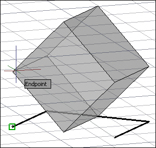
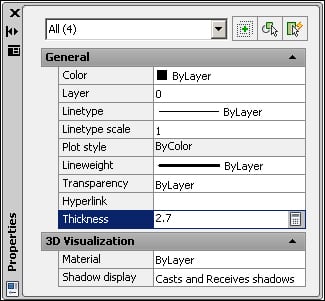
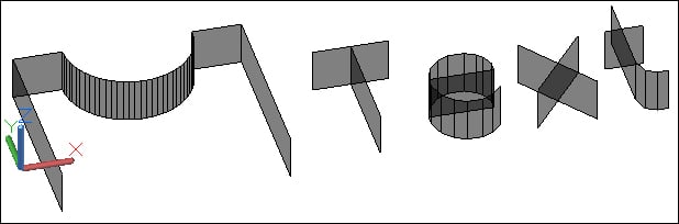
Thickness
Well-nigh all linear entities that we know from 2d have a property called Thickness, whose value represents a acme forth the Z axis (a better word actually should be height). This is the only 3D characteristic available in AutoCAD LT and can exist applied to text (if fabricated with a text manner that uses an SHX font), merely across that is quite limited.
The best mode to change the value of thickness is with the PROPERTIES command, Ctrl + i . A line is still a line or a text still text, but with a proper visualization, these entities can transmit a 3D feeling:
3D polylines
Polylines created with the PLINE control are 2nd, not allowing for vertices with different Z coordinates. These polylines are designed by lightweight polylines. Merely what if a unmarried object is needed to be equanimous past segments whose endpoints accept different Z coordinates?
The respond is to create 3D polylines. Iii processes are available:
-
3DPOLY: This command (alias3P) creates 3D polylines from the showtime. It works like theLINEcommand, but the effect is a unmarried object. -
JOIN: This control (allonymJ) creates 3D polylines from a face-to-face sequence of lines with shared endpoints. It is enough that 1 endpoint of a line is out of the airplane for a 3D polyline to be created. -
PEDIT: The same control (aliasPE) used for the creation of second polylines from lines and arcs can as well exist applied to join lines to a 3D polyline. The commencement object must already be a 3D polyline.
Note
Starting with version 2012, the best way to apply the JOIN control is to select all the line segments at the first command prompt, without specifying a source object. Depending on the type of selected objects and their positions, the nearly suitable object is automatically created.
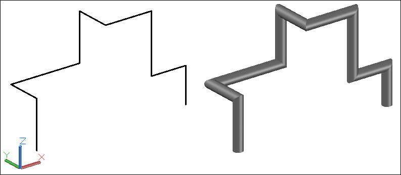
And in what situations may we have utility for 3D polylines?
3D polylines are particularly useful to measure out objects that develop in different directions, such as piping or wiring, and to define paths for other 3D objects such equally piping. The cosmos of 3D solids and surfaces from linear objects is the subject of Chapter four, Creating Solids and Surfaces from 2D .
Splines and helixes
Splines are smooth linear objects, normally without corners that pass through or near specified points. Spline is short for Nonuniform Rational B-Spline ( NURBS ). Splines are described past a gear up of parametric mathematical equations, but accept no fear, for AutoCAD will internally bargain with this, we will non take to!
Splines are used whenever we need smooth curves and are likewise the foundation for NURBS surfaces, the most used surfaces in the automotive or aeronautic projects.
To create a spline we apply the (guess?) SPLINE command (allonym SPL). By default, the command merely prompts for the location of fit points, and the spline passes through the specified points. An Enter finishes the spline and the Shut option creates a airtight spline.
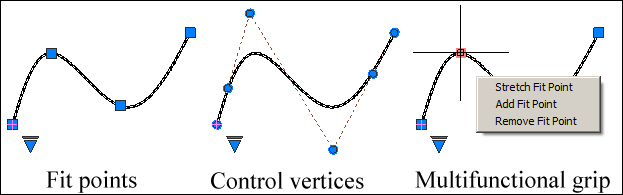
We can control splines by two sets of vertices:
-
Fit points: These are the points used to create the spline -
Control vertices: These are the points that define the spline
When selected, the small blueish triangle allows switching between Fit points and Control vertices. To edit a spline is very simple: we select information technology, without command, and work with grips. We can either click a grip and move it, or we tin identify the cursor over a grip and on the grip menu choose to move the vertex, add one, or remove that vertex. This terminal process is known as multifunctional grip.
Notation
Since AutoCAD 2012, the Join command is also a neat tool for the cosmos of complex splines. We may take a contiguous and non-planar sequence of lines, arcs, elliptical arcs, splines that the effect is a single spline.
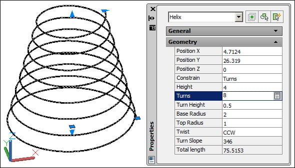
With the HELIX command we tin can create 2D or 3D helixes or spirals. By default, the control prompts for the center point of the base, base of operations radius, superlative radius, and acme. As options, we have the position of the axis endpoint, the number of turns, the height of ane complete turn, and the twist (if the helix is drawn in the clockwise or the counterclockwise management). To edit a helix object, we tin can use grips or the Properties command.
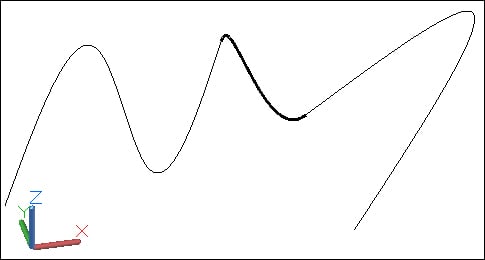
If we explode a helix object, the effect is a spline. The Blend control, new in Version 2012, creates a special spline that connects two open linear objects. The command only prompts for the selection of the first bend and the selection of the second bend. Selections must be near the endpoints to connect. The Continuity option allows for the choice of the applied type of continuity: Tangent with a tangency continuity (known every bit G1 continuity), or Shine with a curvature continuity (known as G2).
How to create great 3D models
In that location are several possibilities for starting a 3D project. We may:
-
Create a 3D project from a complete prepare of second drawings, with all the necessary views included. Hither, we don't accept to project or idealize; we only take to determine the all-time arroyo and the commands that are to be used.
-
Create a 3D project from a plant view and some other elements. Here we accept to projection a lot and probably have to study several possibilities in social club to discover the most suitable projection.
-
Create a 3D projection from scratch. We have naught except some conditions almost space, functionality, or others.
For any of these possibilities, the keyword is planning.
Start, we accept to carefully plan the work. Instead of immediately starting to model, it's better and less time-consuming to decide a draft sequence of tasks.
Some important questions at this phase:
-
Do I have access to something similar?
-
How complex will my project exist?
-
Do I have some 3D blocks that I may utilise?
-
Have I created the needed layers and other definitions (layouts, styles, and then on) in some other projection?
-
Am I going to use external references in my project?
-
Do I take all the necessary information?
If we have 2d drawings, these must be carefully studied, particularly if at that place are any inconsistencies between views and how to outset.
Adjacent, we ready our model. We can open the most important 2D drawing and save it with a different name; we tin can offset a cartoon and insert the other drawings every bit blocks or external references. We must verify if units are coherent, past applying the UNITS command.
Continuing set, we create layers and other definitions. A winning command here is ADCENTER, also known as Design Center ( Ctrl + 2 ) that allows for gathering all layers, blocks, and other definitions from other drawings without opening them.
If nosotros pretend to make some nice realistic images (rendering), nosotros must be careful with layers, knowing that the easiest way to assign materials is past layer.
Should nosotros first from floor plans or elevations? Well, it depends on the project. We can model from plans, merely some parts may come from other views and and then exist positioned.
A final piece of advice is to keep several versions of your projection. When an important step is achieved, we must save a fill-in re-create. If we change our mind almost a step or if the current file is corrupted, we minimize the losses.
Summary
In this chapter, nosotros were introduced to 3D. We saw the importance of the 3rd coordinate, how to enter points in absolute or relative coordinates, and the application of bespeak filters. We analyzed workspaces and how to control the AutoCAD environment. The importance of layers, transparency, and other properties were then explained. Auxiliary tools were then covered before we looked at how to use them to ease the 3D projection. We then saw the awarding of those commands in 3D used daily and some that are especially important, such as BOUNDARY. We too covered the linear 3D commands and the Thickness belongings. We concluded the affiliate by covering adept practices when modeling in 3D.
brannonvirinarlecou.blogspot.com
Source: https://www.packtpub.com/hardware-and-creative/autodesk-autocad-2013-practical-3d-drafting-and-design
0 Response to "draw in 3d autocad 2013"
Post a Comment